

In many asphalt mixing plant projects, environmental monitoring results are often ideal in the initial stages of operation. Equipment is configured correctly, parameters are normal, and emission data fully meet requirements. However, as production load increases and operating time lengthens, emission fluctuations begin to appear, even becoming more frequent. Faced with this situation, the problem is often simplified to whether the environmental protection equipment is inadequate.
In fact, in actual engineering, emissions are never solely determined by the quality of the equipment. They are the engineering manifestation of the long-term combined effects of structural design, flue gas path, and system sealing. When these fundamental conditions continuously change during operation, emission fluctuations are almost inevitable.
Why Emission Instability Has Become a Common Challenge in the Industry?
Over the past few years, initial compliance followed by subsequent fluctuations has become a common experience for asphalt mixing plants in environmental protection operations. Multiple industry surveys and project operation feedback show that more than half of the in-service mixing plants experience varying degrees of emission fluctuations after a period of continuous operation, with the problems often concentrated within 6-18 months after commissioning. This is not a problem of individual equipment or a single brand, but rather a systemic result of multiple industry changes.
Changes in Emission Requirements: From Result Compliance to Process Stability
According to feedback from project operations and maintenance in multiple locations, over 60% of the problems identified during recent environmental inspections did not originate at the moment of testing, but rather stemmed from emission fluctuations recorded during operation. Some projects, even those meeting test standards, were still required to rectify issues due to unstable operational data.
- The change lies in the shift in environmental regulatory focus from one-time test results to a comprehensive assessment of the continuous operation and emission fluctuations of asphalt mixing plants. Tolerance for outliers and short-term fluctuations has significantly decreased.
- The impact is that under this regulatory logic, emissions are no longer considered merely a matter of compliance at a single test moment, but rather a long-term operational indicator that needs to remain stable throughout the entire production cycle.
- The ultimate result is that even if equipment meets environmental standards during testing, frequent or significant emission fluctuations during actual production are easily identified as insufficient system stability, rather than being considered an occasional problem.
Changes in Equipment Operating Cycles: Long-Term Operation Becomes the Norm
Industry statistics show that in most medium and large-scale projects, asphalt mixing plants generally operate continuously for more than 8–12 hours per day. Some highway or airport projects even maintain near full-load operation for a long time. This operating condition is significantly higher than the operating intensity in the early design verification stage.
- The change lies in the fact that with the expansion of project scale and changes in production organization methods, more and more asphalt mixing plants need to operate continuously for extended periods under high-load conditions.
- The impact is that equipment is no longer in an ideal short-cycle, low-intensity operating state, but rather subjected to the combined effects of high temperatures, vibrations, thermal expansion and contraction, and negative pressure environments over long periods.
- The ultimate result is that structural deviations and seal degradation that are not obvious during initial operation will gradually become apparent during long-term operation, directly affecting emission stability.
Changes in equipment design verification focus: More emphasis on commissioning than long-term operating conditions
According to project failure statistics, more than 70% of emission anomalies did not occur in the early stages of production, but rather occurred after 6 months to 1 year of operation. Most of the problems were related to loose interfaces, structural deformation, or decreased sealing performance.
- The change lies in the fact that during the equipment design, manufacturing, and delivery phases, the industry generally focuses more on whether the equipment can be successfully commissioned and meet initial emission requirements, while lacking systematic verification of the structure and sealing condition after long-term operation.
- The resulting impact is that equipment often performs stably in the initial delivery phase, but this performance reflects the state under ideal conditions rather than the actual operating capacity under complex conditions.
- The ultimate result is that when the equipment enters a long-term, high-load operation phase, emission stability begins to decline, resulting in a common phenomenon of initial compliance followed by later fluctuations.
Changes in system complexity: Emissions are more easily amplified
In the completed analyses of emission anomaly cases, more than half of the problems did not originate in the dust collector itself, but rather in pipe interfaces, structural connection nodes, or system pressure regulation points. These problems are often difficult to detect directly during single-point inspections, but they will continue to amplify in operational data, eventually triggering emission anomalies.
- The change lies in the fact that the emission system of an asphalt mixing plant involves multiple equipment, pipelines, and connection nodes, with a complex overall structure and high coupling between various components.
- The resulting impact is that any local change can be transmitted through the system, affecting the overall operating status, and the problem often does not directly appear at the emission end.
- The end result is that emissions instability has gradually evolved from a problem in individual projects into a systemic challenge faced by the entire industry.
Emission System: Operation and Key Characteristics
Faced with the dilemma of initial compliance followed by subsequent fluctuations, simply looking at the performance of a single device is no longer sufficient. We must look at the emissions issue from a more fundamental perspective—how the entire emissions system operates, and how each link, each pipe, and each interface determines long-term stability. To truly understand why emissions fluctuate, we must first understand the system’s operating logic and inherent characteristics, analyzing it as a whole, rather than focusing solely on end-point devices.
How does the emission system operate?
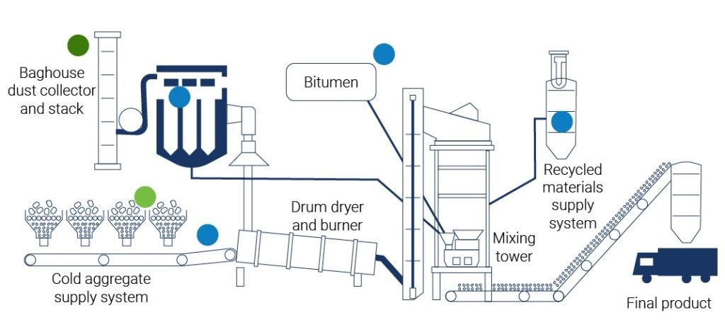
The emission system of an asphalt hot mix plant is not an independent device, but a process chain that runs through the core production stages. Its operation begins with heat generation and ends with the discharge of purified gas. The process can be clearly divided into the following sequential stages:
Starting Point: Flue Gas Generation and Primary Mixing
- The drying drum and burner are the starting point of the system. The burner generates a high-temperature flame, heating the aggregate and evaporating moisture within the drying drum. The high-temperature flue gas generated in this process is the carrier for all subsequent processes.
- Core Function: This determines the initial flue gas temperature, flow rate, and initial dust load.
Transmission: Flue Gas Collection and Transportation
- The high-temperature flue gas, carrying evaporated moisture and fine dust separated from the aggregate, leaves the drying drum.
- Core Function: The piping system forms a closed transmission network. It guides the flue gas to the next stage through negative pressure. Its design directly affects airflow resistance, velocity, and whether dust will settle midway.
Core: Pollutant Separation and Capture
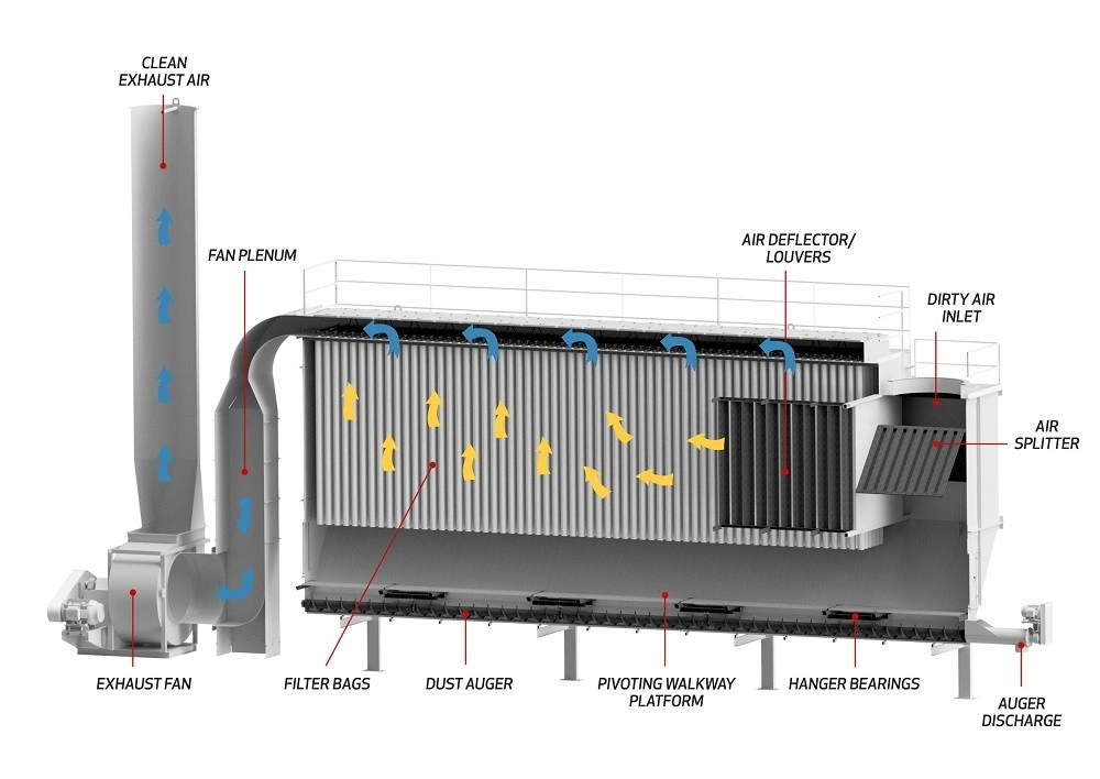
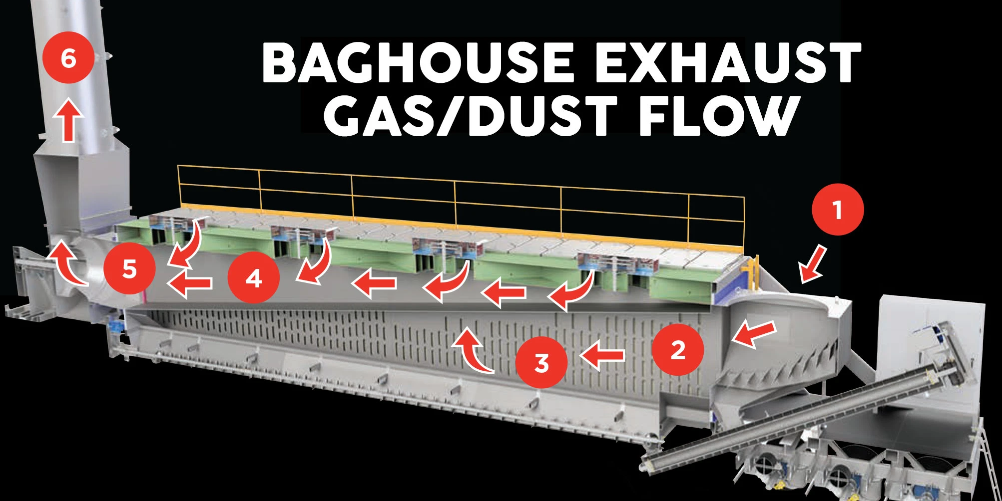
- The flue gas enters the bag filter (core purification equipment). Dust-laden flue gas passes through filter bags, where dust is trapped on the filter bag surface, forming a filter cake; the purified gas then passes through the filter bags.
- Core Function: This is the key step in separating pollutants (dust) from clean gas. Its efficiency is the technological foundation for achieving emission standards.
Power Source: The Heart of the System
- The induced draft fan, located after the dust collector, is the power source for the entire flue gas path. It continuously draws air, establishing and maintaining a stable negative pressure within the system, ensuring that the flue gas flows along the designed path and overcomes all resistance.
- Core Function: Providing power and controlling the airflow balance and pressure distribution of the entire system.
Emission data is the status display at the end of this process chain. Flue gas flows sequentially through: combustion generation → duct transportation → dust removal and purification → fan-driven discharge. Changes in the status of any of these stages will alter the flue gas conditions flowing downstream and ultimately affect the final emission results.
Three Systemic Characteristics of Emission Systems
- Full-Process Interconnectivity: The emission concentration at the end-of-pipe monitoring point is the actual result of the combined effects of all the aforementioned links. Every upstream process parameter, such as changes in drum temperature and airflow, will transmit and affect the end-of-pipe result.
- Structural Complexity and Node Vulnerability: From the drum to the chimney, the flue gas path is tens of meters long, connecting multiple large pieces of equipment in series and linked by numerous flanges, locking devices, access doors, and expansion joints. Each connection point is a potential leak point or a point of resistance variation.
- Dynamic Coupling and Amplification Effect: The subsystems are tightly coupled through airflow and pressure, forming a dynamically balanced whole. The operating point of the induced draft fan depends on the total system resistance, which in turn is determined by the condition of each section of pipeline and each piece of equipment.
From the drying drum to the induced draft fan, the emission system of an asphalt mixing plant is a tightly connected process chain, with each link affecting downstream airflow, temperature, and dust conditions. The full-process interconnectivity, structural complexity, and dynamic coupling of the subsystems mean that emission stability is not the result of a single piece of equipment, but rather the result of the entire system working collaboratively. Only by understanding these operating logics and inherent characteristics can we truly see the root cause of emission fluctuations.
Structural Design: The Physical Basis of Emission Stability
Having understood the emission system as a series of dynamically coupled processes, the issue of emission stability is no longer merely a matter of equipment selection; its stability is largely influenced by structural design. The flue gas path, equipment interfaces, piping layout, support rigidity, and the arrangement of system nodes all directly determine the stability of airflow, pressure, and dust distribution. An unreasonable structure is often the root cause of emission fluctuations and subsequent instability.
Flue Gas Path Structure – Airflow Turbulence Leading to Fluctuations
- Sharp Bends and Abrupt Changes in Cross-Section: Sharp bends and changes in cross-section create eddies and stagnant flow, causing dust to deposit and be re-entrained during airflow fluctuations, resulting in instantaneous emission fluctuations.
- Uneven Distribution of Inlet Air and Feed: Uneven interface layout leads to uneven airflow distribution within the dust collector and ductwork, causing some filter bags to be overloaded and resulting in significant fluctuations in dust removal efficiency.
- Path Length and Accumulated Flow Resistance: Long paths increase the total system resistance, and local disturbances easily accumulate and amplify to the final emission level.
Equipment Interfaces and Support Structure – Leakage and Pressure Disturbances
- Interface Misalignment or Loosening: Slight misalignment of flanges, bolts, or welds can cause localized air leakage, introducing cold air or disturbing the airflow, affecting the downstream flue gas velocity.
- Support Fatigue and Vibration: Long-term vibration or insufficient support can cause interface loosening, fretting wear, or structural deformation, gradually accumulating into emission fluctuations.
- Effects of Thermal Expansion and Contraction: The temperature difference between the high-temperature drum and the ambient-temperature dust collector changes the shape of the duct and interfaces, altering local flow resistance and pressure distribution.
Number of System Nodes – Sensitivity and Amplification Effects
- Too Many Nodes: Each additional flange, expansion joint, or access door increases the potential for leaks or changes in flow resistance, making the system more sensitive to local variations.
- Series Complexity: Connecting multiple devices in series can amplify local pressure or flow abnormalities, affecting the stability of end-of-pipe emissions.
- Accumulation of Local Problems: When pipelines are too long or poorly laid out, small problems gradually accumulate within the system, eventually manifesting as fluctuations in end-of-pipe emissions.
Pipeline and Dust Collector Interface Layout – Local Deposition and Uneven Filter Bag Load
- Inappropriate Interface Location: Causes dust to accumulate locally in the pipeline or at the dust collector inlet, which is then stirred up by airflow fluctuations, resulting in emission fluctuations.
- Uneven Arrangement of Inlets or Baffles: Causes uneven filter bag loads, with some filter bags overloaded and prematurely worn, while others are underutilized.
- Uneven Exhaust Distribution: Affects the uniformity of airflow within the dust collector, reducing overall dust removal efficiency and increasing end-of-pipe emission fluctuations.
Support and Rigid Structures – Potential Risks to Long-Term Stability
- Uneven support arrangement: Vibration amplifies local interface displacements, leading to long-term instability in the flue gas flow field and pressure distribution.
- Fatigue in structurally weak areas: Long-term vibration causes weld cracking, flange loosening, or micro-deformation of pipelines, resulting in system leaks.
- Lack of dynamic compensation: The structure cannot adapt to temperature changes or vibration, leading to changes in local flow resistance and emission fluctuations.
The stability of an emission system is influenced by multiple factors in its structural design: flue gas path, interfaces and supports, system node layout, dust collector interface layout, and support rigidity. Each of these factors can potentially become a source of emission fluctuations. Understanding these influencing factors and their mechanisms can explain why some asphalt mixing plants initially meet emission standards but experience frequent emission fluctuations after long-term operation.
Sealing: The Key Factor for Long-Term Emission Stability
In emission systems, sealing is crucial for long-term stability. It not only affects emissions during a single operation but also determines the system’s performance under long-term, high-load, and thermal cycling conditions. The key is not the presence of leaks, but the ability to maintain leak-free operation over the long term. Sealing issues gradually manifest over time due to thermal stress and vibration, and are amplified through the system, impacting overall emission stability. The following are some key influencing factors and their analysis:
Number and Distribution of Sealing Points
- More interfaces, higher failure probability: The more interfaces on pipe flanges, expansion joints, inspection doors, and dust collectors, the more likely each one is to become a source of leakage, increasing the overall system leakage risk.
- Dynamic parts are more prone to failure: Thermal expansion and contraction, vibration, or frequent equipment start-ups and shutdowns can make dynamic interfaces such as expansion joints and rotary valves leak points, affecting local pressure and airflow stability.
- Uneven distribution leads to local pressure disturbances: Sealing points concentrated in the same area can create local airflow disturbances, amplifying the impact on downstream emissions.
Sealing Material Durability
- High-temperature environments accelerate aging: Long-term high temperatures can cause sealing materials to harden and become brittle, reducing sealing performance and gradually increasing leakage.
- Oil, gas, and dust erosion: Oil, asphalt residue, and dust in flue gas can adhere to the sealing surface, reducing friction performance or damaging the seals.
- Material fatigue and performance degradation: Seals subjected to pressure, vibration, and thermal cycling over a long period of time will gradually develop micro-cracks or deformation, leading to a decrease in system sealing performance.
Amplification Effects of Localized Seal Failure
- Even minor leaks can affect the overall system pressure: Even tiny leaks can alter the negative pressure distribution of the system, causing changes in flue gas velocity and path.
- Localized leaks cause filter bag load fluctuations: Leaking areas can cause some filter bags to experience decreased or increased loads, leading to uneven dust removal efficiency and affecting end-point emissions.
- System coupling effect amplifies fluctuations: Through airflow and pressure coupling, disturbances caused by localized leaks are transmitted and amplified, manifesting as overall emission fluctuations.
Difficulty in Seal Maintenance
- Interfaces difficult to inspect regularly: Seals located at high altitudes, in narrow spaces, or in complex structures are easily overlooked. Small leaks accumulate over time, ultimately affecting overall emissions.
- High maintenance difficulty of dynamic interfaces: Components requiring frequent operation, such as rotary valves and expansion joints, are difficult to maintain and pose a greater risk of seal failure.
- Invisible aging and wear: Micro-cracks or material hardening inside seals are difficult to detect, accumulating slowly over long-term operation and leading to increased system leakage.
How Structural and Sealing Issues Are Amplified During Operation
Structural and sealing issues may be minor and difficult to detect during the design or installation phase, but they can be gradually amplified during long-term operation due to changes in system conditions, operating loads, and the environment, ultimately having a significant impact on emission stability.